Brakes Temperature Indication on the WHEEL SD page
| 32-07-01A | Brakes Temperature Indication on the WHEEL SD page |
|---|
Applicable to: -
- Flight Preparation/Limitations
The brake energy graph and the
brake cooling time table given hereafter permit to determine the ground
brake cooling time.
BRAKE ENERGY GRAPH
If MAX reverser thrust was selected for all reversers during
the braking phase:
Enter the brake energy
graph: WITH THRUST REVERSERS USE.
If MAX reverser thrust was NOT selected for all reversers during
the braking phase:
Enter the brake energy
graph: WITHOUT THRUST REVERSERS USE.
Determination of the brake
energy accumulated during a REJECTED TAKEOFF (RTO) :
- Enter with the aircraft takeoff weight (TOW) and with the rejected takeoff speed in kt IAS).
- Apply airport pressure altitude, temperature, wind and runway slope corrections.
Determination of the brake energy
accumulated during a LANDING :
- Enter with the aircraft landing weight, and
- Enter with the touch down speed in kt IAS if the autobrake was selected and applied or with the manual braking speed in kt IAS in the other cases.
- Apply airport pressure altitude, temperature, wind and runway slope corrections.
- Correct for brake setting with a preselected autobrake setting (LO, MED) or with MAX PEDAL braking in the other cases.NOTE:In the case of a dispatch with one brake inoperative ( Refer to item 01 Main Wheel Brake or Refer to item 02 Green System Brake), the brake energy accumulated is increased by 34 %.
Brake Energy with Thrust Reverser Use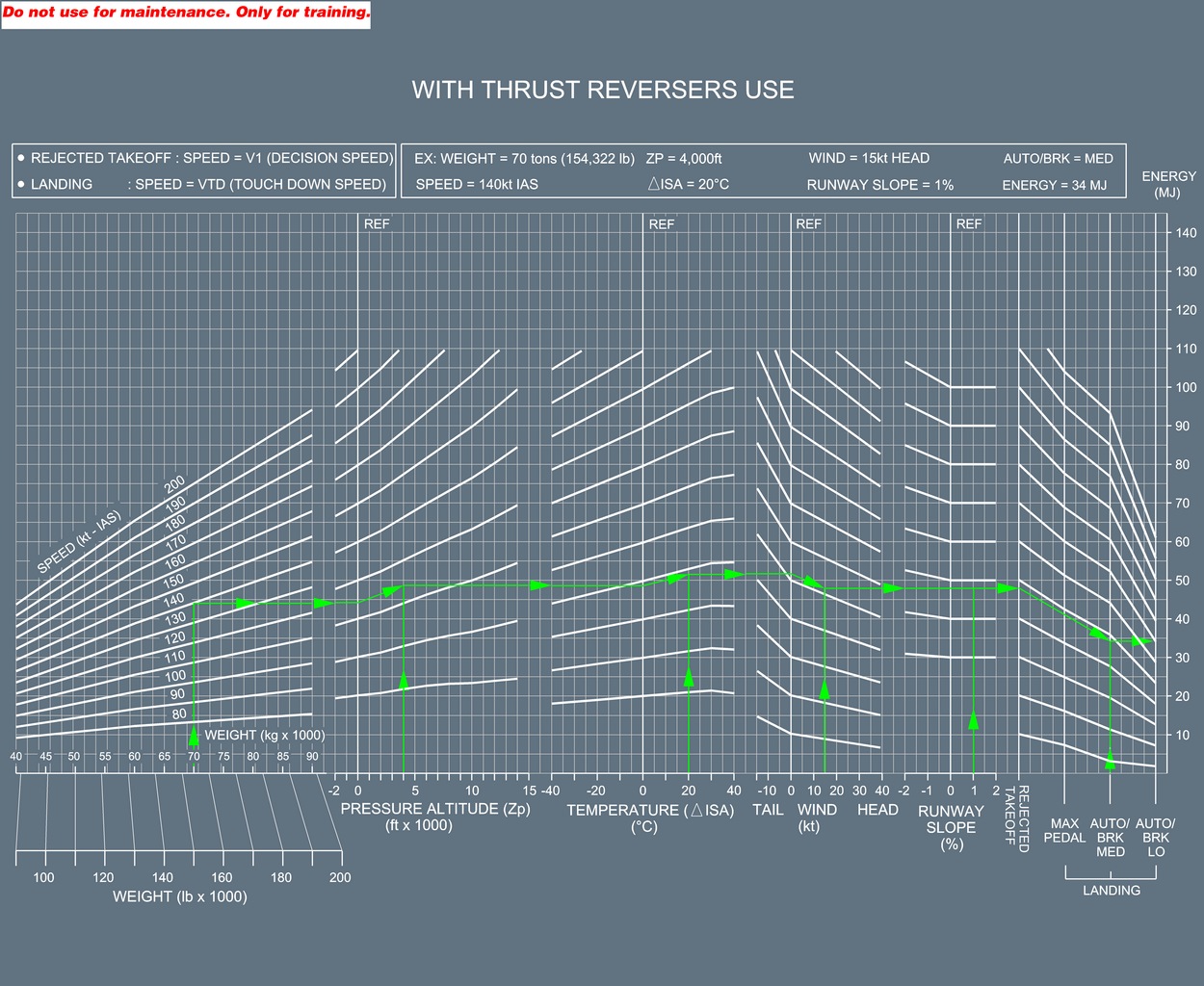
Brake Energy without Thrust Reverser Use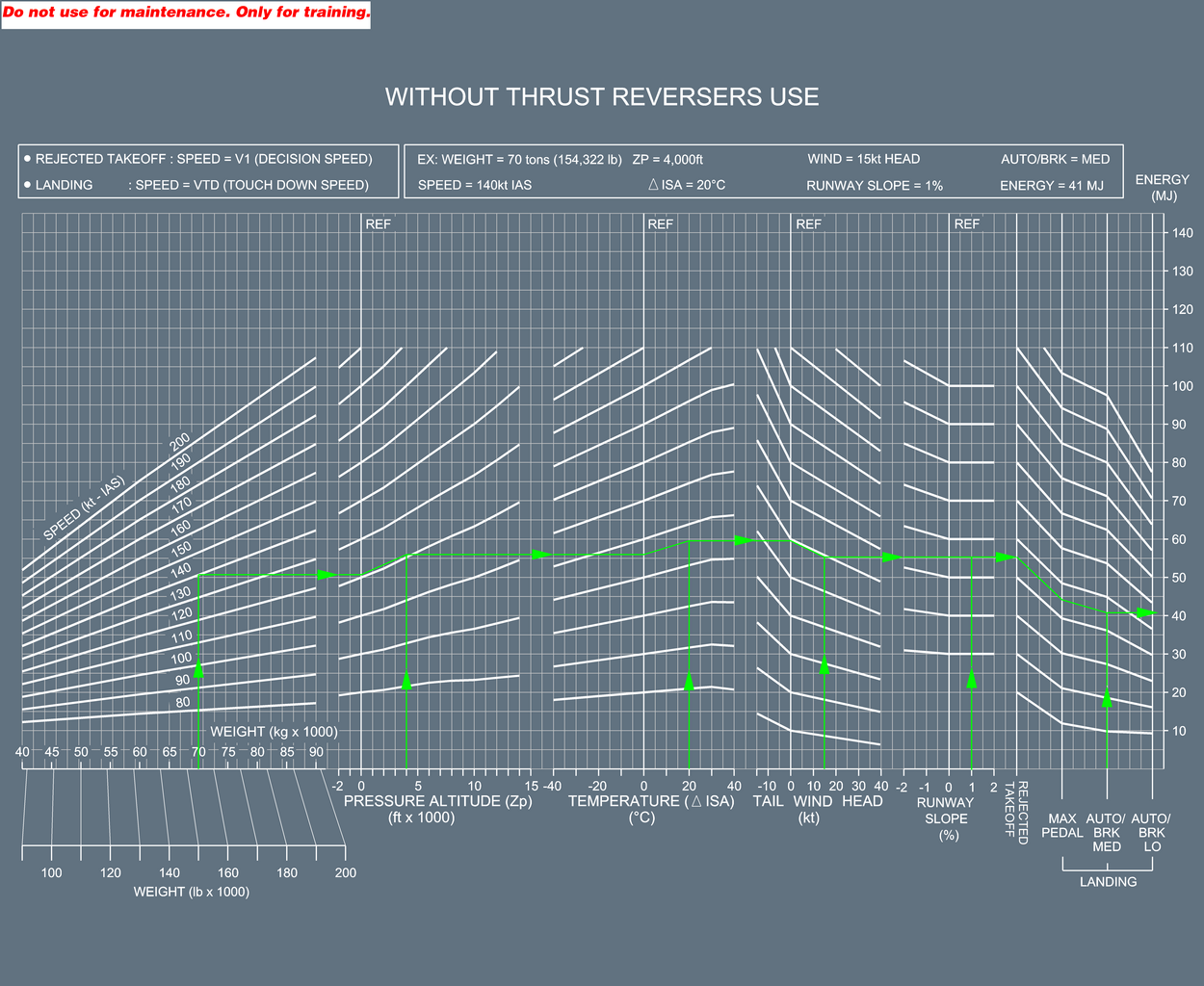
Brake Cooling Time Table
Determination of the brake cooling time:
EXAMPLE:
| 25 | 99 49 | 90 45 | 94 46 | 97 48 | 100 50 | ====> TIME (min)
WITHOUT BRAKE COOLING FAN ====> TIME (min)
WITH BRAKE COOLING FAN | ||||||
If the Energy and the OAT are not given in the table,
use the values given in the next adjacent column/row.
For Example, with Energy = 25 MJ, and OAT = 15 °C, entering the next adjacent column/row (Energy
= 25 MJ, OAT = 20 °C) gives
the following results:
- Without brake cooling fan: 112 min
- With brake cooling fan: 55 min
Enter the following table with the energy and the OAT to
determine the ground brake cooling time.
GROUND BRAKE COOLING
TIME (min) | ||||||||||||
|---|---|---|---|---|---|---|---|---|---|---|---|---|
ENERGY (MJ) | OAT (°C) | |||||||||||
| -50 | -40 | -30 | -20 | -10 | 0 | 10 | 20 | 30 | 40 | 50 | 55 | |
| 0 | 28 | 14 | 17 | 20 | 23 | 26 | 29 | 34 | 39 | 45 | 52 | 56 |
| 14 | 7 | 9 | 10 | 11 | 13 | 15 | 17 | 20 | 23 | 26 | 28 | |
| 5 | 52 | 41 | 44 | 48 | 50 | 54 | 57 | 62 | 67 | 73 | 80 | 84 |
| 26 | 20 | 22 | 24 | 25 | 27 | 28 | 31 | 33 | 36 | 40 | 42 | |
| 10 | 69 | 58 | 62 | 65 | 68 | 72 | 75 | 80 | 85 | 91 | 98 | 102 |
| 34 | 29 | 31 | 32 | 34 | 36 | 37 | 39 | 42 | 45 | 49 | 51 | |
| 15 | 81 | 71 | 75 | 78 | 81 | 85 | 88 | 93 | 98 | 105 | 112 | 116 |
| 40 | 35 | 37 | 39 | 40 | 42 | 44 | 46 | 49 | 52 | 55 | 57 | |
| 20 | 91 | 82 | 85 | 89 | 92 | 95 | 99 | 103 | 109 | 115 | 122 | 126 |
| 45 | 40 | 42 | 44 | 45 | 47 | 49 | 51 | 54 | 57 | 60 | 62 | |
| 25 | 99 | 90 | 94 | 97 | 100 | 104 | 108 | 112 | 118 | 124 | 131 | 135 |
| 49 | 45 | 46 | 48 | 50 | 51 | 53 | 55 | 58 | 61 | 65 | 67 | |
| 30 | 106 | 98 | 101 | 105 | 108 | 111 | 115 | 119 | 125 | 131 | 138 | 142 |
| 53 | 48 | 50 | 52 | 53 | 55 | 57 | 59 | 62 | 65 | 68 | 70 | |
| 35 | 113 | 104 | 108 | 111 | 114 | 118 | 121 | 126 | 131 | 138 | 145 | 149 |
| 56 | 51 | 53 | 55 | 56 | 58 | 60 | 62 | 65 | 68 | 71 | 73 | |
| 40 | 118 | 110 | 113 | 117 | 120 | 124 | 127 | 132 | 137 | 143 | 150 | 154 |
| 58 | 54 | 56 | 58 | 59 | 61 | 63 | 65 | 68 | 71 | 74 | 76 | |
| 45 | 123 | 115 | 118 | 122 | 125 | 129 | 132 | 137 | 142 | 149 | 156 | 160 |
| 61 | 57 | 58 | 60 | 62 | 64 | 65 | 68 | 70 | 73 | 77 | 79 | |
| 50 | 128 | 120 | 123 | 127 | 130 | 133 | 137 | 141 | 147 | 153 | 160 | 164 |
| 63 | 59 | 61 | 62 | 64 | 66 | 68 | 70 | 73 | 76 | 79 | 81 | |
| 55 | 132 | 124 | 127 | 131 | 134 | 138 | 141 | 146 | 151 | 158 | 165 | 169 |
| 65 | 61 | 63 | 65 | 66 | 68 | 70 | 72 | 75 | 78 | 81 | 83 | |
| 60 | 136 | 128 | 131 | 135 | 138 | 142 | 145 | 150 | 155 | 161 | 169 | 173 |
| 67 | 63 | 65 | 67 | 68 | 70 | 72 | 74 | 77 | 80 | 83 | 85 | |
| 65 | 139 | 131 | 135 | 138 | 142 | 145 | 149 | 153 | 159 | 165 | 172 | 176 |
| 69 | 65 | 67 | 68 | 70 | 72 | 73 | 76 | 78 | 81 | 85 | 87 | |
| 70 | 143 | 135 | 138 | 142 | 145 | 149 | 152 | 157 | 162 | 169 | 176 | 180 |
| 70 | 67 | 68 | 70 | 72 | 73 | 75 | 77 | 80 | 83 | 87 | 89 | |
| 75 | 146 | 138 | 141 | 145 | 148 | 152 | 156 | 160 | 166 | 172 | 179 | 183 |
| 72 | 68 | 70 | 72 | 73 | 75 | 77 | 79 | 82 | 85 | 88 | 90 | |
| 80 | 149 | 141 | 144 | 148 | 151 | 155 | 159 | 163 | 169 | 175 | 182 | 186 |
| 73 | 70 | 71 | 73 | 75 | 76 | 78 | 80 | 83 | 86 | 90 | 92 | |
- After Engine Start
In the case of a false BRAKES HOT alert displayed on the EWD:
- EMER CANC pbPress
NOTE:
In the case of a false BRAKES HOT alert due to a faulty BTMU or a faulty BSCU, the "T.O CONFIG NORMAL” line will
not replace the "T.O CONFIG . . TEST" line in the T.O MEMO.
Consider normal configuration for takeoff provided that no alert was
displayed during the T.O CONFIG TEST.
| CAUTION: | The T.O CONFIG
TEST pb must be maintained pressed to check that there is no alert. |
| 32-07-01A | Brakes Temperature Indication on the WHEEL SD page |
|---|
Applicable to: -
- Flight Preparation/Limitations
The brake energy graph and the
brake cooling time table given hereafter permit to determine the ground
brake cooling time.
BRAKE ENERGY GRAPH
If MAX reverser thrust was selected for all reversers during
the braking phase:
Enter the brake energy
graph: WITH THRUST REVERSERS USE.
If MAX reverser thrust was NOT selected for all reversers during
the braking phase:
Enter the brake energy
graph: WITHOUT THRUST REVERSERS USE.
Determination of the brake
energy accumulated during a REJECTED TAKEOFF (RTO) :
- Enter with the aircraft takeoff weight (TOW) and with the rejected takeoff speed in kt IAS.
- Apply airport pressure altitude, temperature, wind and runway slope corrections.
Determination of the brake energy
accumulated during a LANDING :
- Enter with the aircraft landing weight, and
- Enter with the touch down speed in kt IAS if the autobrake was selected and applied or with the manual braking speed in kt IAS in the other cases.
- Apply airport pressure altitude, temperature, wind and runway slope corrections.
- Correct for brake setting with a preselected autobrake setting (LO, MED) or with MAX PEDAL braking in the other cases.NOTE:In the case of a dispatch with one brake inoperative ( Refer to item 01 Main Wheel Brake or Refer to item 02 Green System Brake), the brake energy accumulated is increased by 34 %.
Brake Energy with Thrust Reverser Use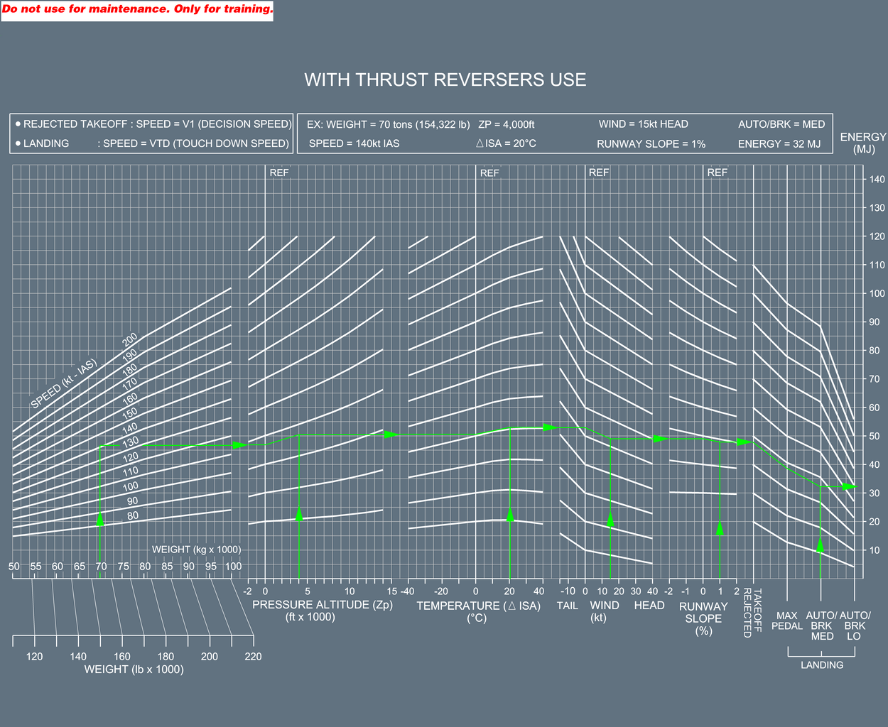
Brake Energy without Thrust Reverser Use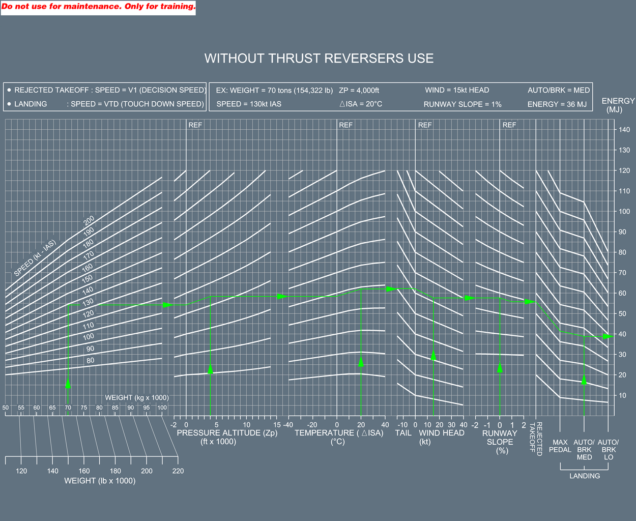
Brake Cooling Time Table
Determination of the brake cooling time:
EXAMPLE:
| 25 | 73 27 | 69 26 | 72 27 | 75 28 | 79 30 | ====> TIME (min)
WITHOUT BRAKE COOLING FAN ====> TIME (min)
WITH BRAKE COOLING FAN | ||||||
If the Energy and the OAT are not given in the table,
use the values given in the next adjacent column/row.
For Example, with Energy = 25 MJ, and OAT = 15 °C, entering the next adjacent column/row (Energy
= 25 MJ, OAT = 20 °C) gives
the following results:
- Without brake cooling fan: 88 min
- With brake cooling fan: 33 min
Enter the following table with the energy and the OAT to
determine the ground brake cooling time.
GROUND BRAKE COOLING
TIME (min) | ||||||||||||
|---|---|---|---|---|---|---|---|---|---|---|---|---|
ENERGY (MJ) | OAT (°C) | |||||||||||
| -50 | -40 | -30 | -20 | -10 | 0 | 10 | 20 | 30 | 40 | 50 | 55 | |
| 0 | 0 | 0 | 0 | 0 | 0 | 0 | 0 | 0 | 0 | 0 | 0 | 2 |
| 0 | 0 | 0 | 0 | 0 | 0 | 0 | 0 | 0 | 0 | 0 | 1 | |
| 5 | 11 | 5 | 8 | 11 | 13 | 16 | 19 | 23 | 27 | 32 | 37 | 39 |
| 4 | 2 | 3 | 4 | 5 | 6 | 8 | 9 | 10 | 12 | 14 | 15 | |
| 10 | 33 | 28 | 31 | 34 | 37 | 40 | 43 | 46 | 51 | 55 | 60 | 63 |
| 12 | 11 | 12 | 13 | 14 | 15 | 16 | 18 | 19 | 21 | 23 | 24 | |
| 15 | 49 | 45 | 48 | 51 | 54 | 57 | 60 | 63 | 68 | 72 | 77 | 80 |
| 19 | 17 | 18 | 19 | 20 | 21 | 23 | 24 | 26 | 27 | 29 | 30 | |
| 20 | 62 | 58 | 61 | 64 | 67 | 70 | 74 | 77 | 81 | 86 | 91 | 93 |
| 23 | 22 | 23 | 24 | 25 | 26 | 28 | 29 | 31 | 32 | 34 | 35 | |
| 25 | 73 | 69 | 72 | 75 | 79 | 82 | 85 | 88 | 93 | 97 | 102 | 105 |
| 27 | 26 | 27 | 28 | 30 | 31 | 32 | 33 | 35 | 36 | 38 | 39 | |
| 30 | 82 | 79 | 82 | 85 | 88 | 91 | 95 | 98 | 102 | 107 | 112 | 114 |
| 31 | 30 | 31 | 32 | 33 | 34 | 35 | 37 | 38 | 40 | 42 | 43 | |
| 35 | 90 | 87 | 90 | 93 | 96 | 99 | 103 | 106 | 111 | 115 | 120 | 123 |
| 34 | 33 | 34 | 35 | 36 | 37 | 39 | 40 | 41 | 43 | 45 | 46 | |
| 40 | 97 | 95 | 97 | 101 | 104 | 107 | 110 | 114 | 118 | 123 | 127 | 130 |
| 37 | 36 | 37 | 38 | 39 | 40 | 41 | 43 | 44 | 46 | 48 | 49 | |
| 45 | 104 | 101 | 104 | 107 | 110 | 113 | 117 | 120 | 125 | 129 | 134 | 137 |
| 39 | 38 | 39 | 40 | 41 | 42 | 44 | 45 | 47 | 48 | 50 | 51 | |
| 50 | 110 | 107 | 110 | 113 | 116 | 119 | 123 | 126 | 131 | 135 | 140 | 143 |
| 41 | 40 | 41 | 42 | 44 | 45 | 46 | 47 | 49 | 51 | 52 | 53 | |
| 55 | 115 | 113 | 116 | 119 | 122 | 125 | 128 | 132 | 136 | 141 | 146 | 148 |
| 43 | 42 | 43 | 44 | 46 | 47 | 48 | 49 | 51 | 53 | 54 | 55 | |
| 60 | 120 | 118 | 121 | 124 | 127 | 130 | 134 | 137 | 141 | 146 | 151 | 153 |
| 45 | 44 | 45 | 46 | 48 | 49 | 50 | 51 | 53 | 55 | 56 | 57 | |
| 65 | 125 | 123 | 125 | 128 | 132 | 135 | 138 | 142 | 146 | 151 | 155 | 158 |
| 47 | 46 | 47 | 48 | 49 | 50 | 52 | 53 | 55 | 56 | 58 | 59 | |
| 70 | 129 | 127 | 130 | 133 | 136 | 139 | 143 | 146 | 150 | 155 | 160 | 162 |
| 48 | 47 | 49 | 50 | 51 | 52 | 53 | 55 | 56 | 58 | 60 | 61 | |
| 75 | 133 | 131 | 134 | 137 | 140 | 143 | 147 | 150 | 154 | 159 | 164 | 167 |
| 50 | 49 | 50 | 51 | 52 | 54 | 55 | 56 | 58 | 59 | 61 | 62 | |
| 80 | 137 | 135 | 138 | 141 | 144 | 147 | 151 | 154 | 158 | 163 | 168 | 170 |
| 51 | 50 | 52 | 53 | 54 | 55 | 56 | 58 | 59 | 61 | 63 | 64 | |
- After Engine Start
In the case of a false BRAKES HOT alert displayed on the EWD:
- EMER CANC pbPress
NOTE:
In the case of a false BRAKES HOT alert due to a faulty BTMU or a faulty BSCU, the "T.O CONFIG NORMAL” line will
not replace the "T.O CONFIG . . TEST" line in the T.O MEMO.
Consider normal configuration for takeoff provided that no alert was
displayed during the T.O CONFIG TEST.
| CAUTION: | The T.O CONFIG
TEST pb must be maintained pressed to check that there is no alert. |
| 32-07-01A | Brakes Temperature Indication on the WHEEL |
|---|
Applicable to: -
- Flight Preparation/Limitations
The brake energy graph and the brake cooling time table given hereafter
permit to determine the ground brake cooling time.
BRAKE ENERGY
GRAPH
If MAX reverser thrust was selected for all reversers during
the braking phase:
Enter the brake energy
graph: WITH THRUST REVERSERS USE.
If MAX reverser thrust was NOT selected for all reversers during
the braking phase:
Enter the brake energy
graph: WITHOUT THRUST REVERSERS USE.
Determination of the brake
energy accumulated during a REJECTED TAKEOFF (RTO) :
- Enter with the aircraft takeoff weight (TOW) and with the rejected takeoff speed in kt IAS).
- Apply airport pressure altitude, temperature, wind and runway slope corrections.
Determination of the brake energy
accumulated during a LANDING :
- Enter with the aircraft landing weight, and
- Enter with the touch down speed in kt IAS if the autobrake was selected and applied or with the manual braking speed in kt IAS in the other cases.
- Apply airport pressure altitude, temperature, wind and runway slope corrections.
- Correct for brake setting with a preselected autobrake setting (LO, MED) or with MAX PEDAL braking in the other cases.NOTE:In the case of a dispatch with one brake inoperative ( Refer to item 01 Main Wheel Brake or Refer to item 02 Green System Brake), the brake energy accumulated is increased by 34 %.
Brake Energy with Thrust Reverser Use
Brake Energy without Thrust Reverser Use
Brake Cooling Time Table
Determination of the brake
cooling time:
EXAMPLE:
| 55 | 152 46 | 153 46 | 154 46 | 155 46 | 155 47 | ====> TIME (min)
WITHOUT BRAKE COOLING FAN ====> TIME (min)
WITH BRAKE COOLING FAN | ||||||
If the Energy and the OAT are not given in the table,
use the values given in the next adjacent column/row.
For Example, with Energy = 78 MJ, and OAT = 15 °C, entering the next adjacent column/row (Energy = 80 MJ, OAT = 20 °C) gives
the following results:
- Without brake cooling fan: 189 min
- With brake cooling fan: 57 min
Enter the following table with the energy and the OAT to
determine the ground brake cooling time.
GROUND BRAKE COOLING
TIME (min) | ||||||||||||
|---|---|---|---|---|---|---|---|---|---|---|---|---|
ENERGY (MJ) | OAT (°C) | |||||||||||
-50 | -40 | -30 | -20 | -10 | 0 | 10 | 20 | 30 | 40 | 50 | 55 | |
| 0 | 0 0 | 0 0 | 0 0 | 0 0 | 0 0 | 0 0 | 0 0 | 0 0 | 0 0 | 0 0 | 0 0 | 0 0 |
| 5 | 0 0 | 0 0 | 0 0 | 0 0 | 0 0 | 0 0 | 0 0 | 0 0 | 0 0 | 0 0 | 0 0 | 0 0 |
| 10 | 0 0 | 0 0 | 0 0 | 4 1 | 9 3 | 14 4 | 19 6 | 23 7 | 27 8 | 31 9 | 35 10 | 37 11 |
| 15 | 31 9 | 35 10 | 38 11 | 42 12 | 45 13 | 48 14 | 51 15 | 54 16 | 57 17 | 60 18 | 62 19 | 64 19 |
| 20 | 59 18 | 62 19 | 65 19 | 67 20 | 70 21 | 72 22 | 74 22 | 77 23 | 79 24 | 81 24 | 83 25 | 84 25 |
| 25 | 81 24 | 83 25 | 85 25 | 87 26 | 89 27 | 91 27 | 92 28 | 94 28 | 96 29 | 98 29 | 99 30 | 100 30 |
| 30 | 98 29 | 99 30 | 101 30 | 103 31 | 104 31 | 106 32 | 107 32 | 109 33 | 110 33 | 112 34 | 113 34 | 114 34 |
| 35 | 112 34 | 113 34 | 115 34 | 116 35 | 117 35 | 119 36 | 120 36 | 121 36 | 123 37 | 124 37 | 125 38 | 126 38 |
| 40 | 124 37 | 125 37 | 126 38 | 127 38 | 129 39 | 130 39 | 131 39 | 132 40 | 133 40 | 134 40 | 135 41 | 136 41 |
| 45 | 134 40 | 135 41 | 136 41 | 137 41 | 139 42 | 140 42 | 141 42 | 142 42 | 143 43 | 144 43 | 145 43 | 145 44 |
| 50 | 144 43 | 145 43 | 146 44 | 146 44 | 147 44 | 148 45 | 149 45 | 150 45 | 151 45 | 152 46 | 153 46 | 153 46 |
| 55 | 152 46 | 153 46 | 154 46 | 155 46 | 155 47 | 156 47 | 157 47 | 158 47 | 159 48 | 160 48 | 160 48 | 161 48 |
| 60 | 160 48 | 160 48 | 161 48 | 162 49 | 163 49 | 164 49 | 164 49 | 165 50 | 166 50 | 167 50 | 167 50 | 168 50 |
| 65 | 167 50 | 167 50 | 168 50 | 169 51 | 170 51 | 170 51 | 171 51 | 172 52 | 172 52 | 173 52 | 174 52 | 174 52 |
| 70 | 173 52 | 174 52 | 174 52 | 175 53 | 176 53 | 176 53 | 177 53 | 178 53 | 178 54 | 179 54 | 180 54 | 180 54 |
| 75 | 179 54 | 180 54 | 180 54 | 181 54 | 182 54 | 182 55 | 183 55 | 183 55 | 184 55 | 185 55 | 185 56 | 186 56 |
| 80 | 185 55 | 185 56 | 186 56 | 186 56 | 187 56 | 188 56 | 188 56 | 189 57 | 189 57 | 190 57 | 190 57 | 191 57 |
| 85 | 190 57 | 190 57 | 191 57 | 191 57 | 192 58 | 193 58 | 193 58 | 194 58 | 194 58 | 195 58 | 195 59 | 196 59 |
| 90 | 195 58 | 195 59 | 196 59 | 196 59 | 197 59 | 197 59 | 198 59 | 198 60 | 199 60 | 199 60 | 200 60 | 200 60 |
| 95 | 199 60 | 200 60 | 200 60 | 201 60 | 201 60 | 202 61 | 202 61 | 203 61 | 203 61 | 204 61 | 204 61 | 205 61 |
| 100 | 204 61 | 204 61 | 205 61 | 205 62 | 206 62 | 206 62 | 207 62 | 207 62 | 208 62 | 208 62 | 208 63 | 209 63 |
| 105 | 208 62 | 208 63 | 209 63 | 209 63 | 210 63 | 210 63 | 211 63 | 211 63 | 212 63 | 212 64 | 212 64 | 213 64 |
| 110 | 212 64 | 212 64 | 213 64 | 213 64 | 214 64 | 214 64 | 215 64 | 215 64 | 215 65 | 216 65 | 216 65 | 216 65 |
| 115 | 216 65 | 216 65 | 217 65 | 217 65 | 217 65 | 218 65 | 218 65 | 219 66 | 219 66 | 219 66 | 220 66 | 220 66 |
| 120 | 219 66 | 220 66 | 220 66 | 221 66 | 221 66 | 221 66 | 222 67 | 222 67 | 222 67 | 223 67 | 223 67 | 223 67 |
| A320 | Messier/Goodrich -
03.01.05 - F476021.txt | |||||||||||
- After Engine Start
In the case of a false BRAKES HOT alert displayed on the EWD:
- EMER CANC pbPress
NOTE:
In the case of a false BRAKES HOT alert due to a faulty BTMU or a faulty BSCU, the "T.O CONFIG NORMAL” line will not
replace the "T.O CONFIG . . TEST" line in the T.O MEMO. Consider normal
configuration for takeoff provided that no alert was displayed during
the T.O CONFIG TEST.
| CAUTION: | The T.O CONFIG
TEST pb must be maintained pressed to check that there is no alert. |
| 32-07-01A | Brakes Temperature Indication on the WHEEL SD page |
|---|
Applicable to: -
- Flight Preparation/Limitations
The brake energy graph and the brake
cooling time table given hereafter permit to determine the ground
brake cooling time.
BRAKE ENERGY GRAPH
If MAX reverser thrust was selected for all reversers during
the braking phase:
Enter the brake energy
graph: WITH THRUST REVERSERS USE.
If MAX reverser thrust was NOT selected for all reversers during
the braking phase:
Enter the brake energy
graph: WITHOUT THRUST REVERSERS USE.
Determination of the brake
energy accumulated during a REJECTED TAKEOFF (RTO) :
- Enter with the aircraft takeoff weight (TOW) and with the rejected takeoff speed in kt IAS).
- Apply airport pressure altitude, temperature, wind and runway slope corrections.
Determination of the brake energy
accumulated during a LANDING :
- Enter with the aircraft landing weight, and
- Enter with the touch down speed in kt IAS if the autobrake was selected and applied or with the manual braking speed in kt IAS in the other cases.
- Apply airport pressure altitude, temperature, wind and runway slope corrections.
- Correct for brake setting with a preselected autobrake setting (LO, MED) or with MAX PEDAL braking in the other cases.NOTE:In the case of a dispatch with one brake inoperative ( Refer to item 01 Main Wheel Brake or Refer to item 02 Green System Brake), the brake energy accumulated is increased by 34 %.
Brake Energy with Thrust Reverser Use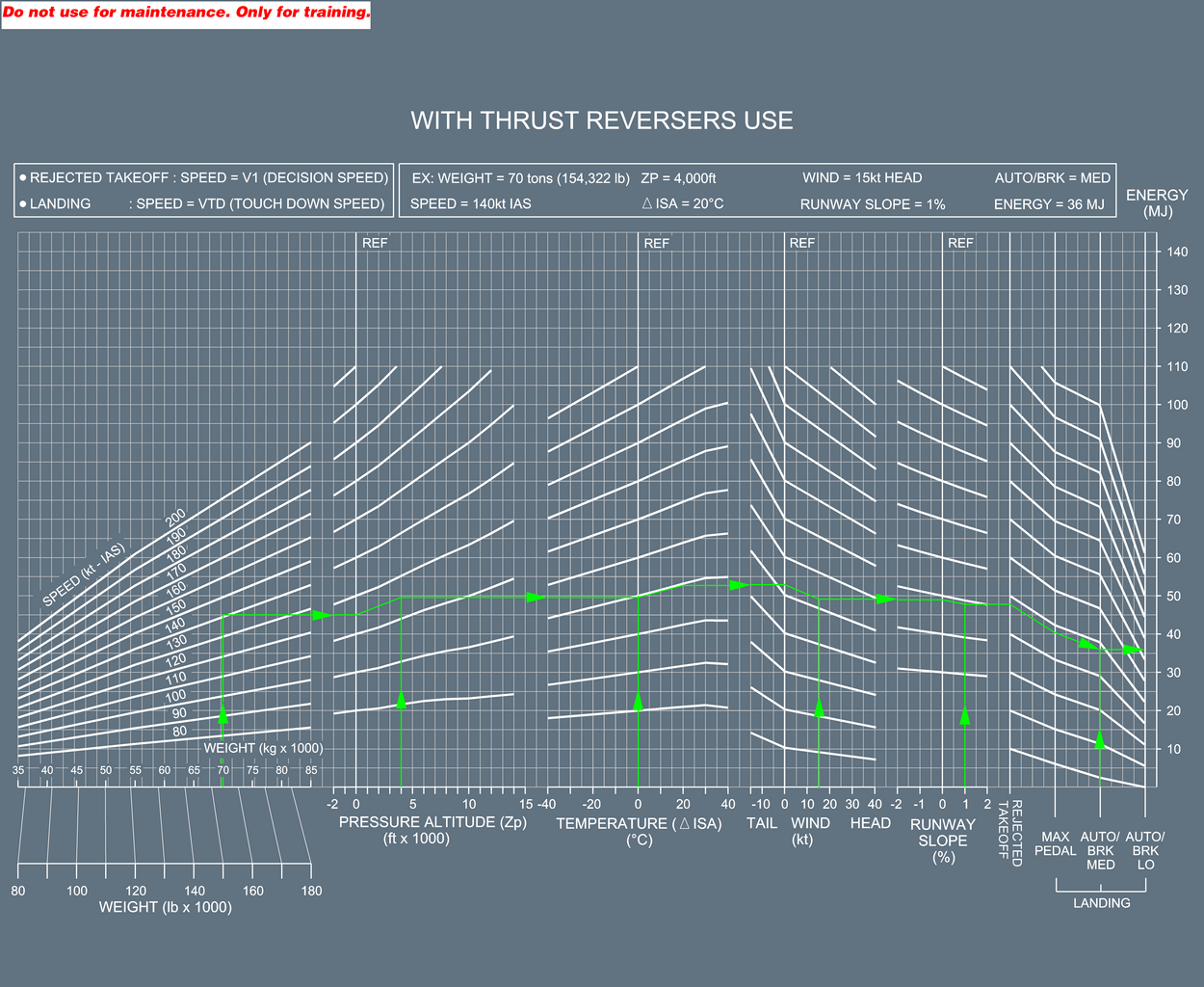
Brake Energy without Thrust Reverser Use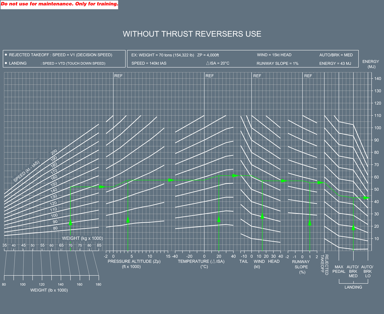
Brake Cooling Time Table
EXAMPLE:
| 55 | 152 46 | 153 46 | 154 46 | 155 46 | 155 47 | ====> TIME (min)
WITHOUT BRAKE COOLING FAN ====> TIME (min)
WITH BRAKE COOLING FAN | ||||||
If the Energy and the OAT are
not given in the table, use the values given in the next adjacent
column/row.
For Example, with Energy = 78 MJ, and OAT = 15 °C, entering the next adjacent column/row
(Energy = 80 MJ, OAT = 20 °C) gives the following results:
- Without brake cooling fan: 189 min
- With brake cooling fan: 57 min
Enter the following table with the energy
and the OAT to determine the ground brake cooling time.
GROUND BRAKE COOLING
TIME (min) | ||||||||||||
|---|---|---|---|---|---|---|---|---|---|---|---|---|
ENERGY (MJ) | OAT (°C) | |||||||||||
-50 | -40 | -30 | -20 | -10 | 0 | 10 | 20 | 30 | 40 | 50 | 55 | |
| 0 | 0 0 | 0 0 | 0 0 | 0 0 | 0 0 | 0 0 | 0 0 | 0 0 | 0 0 | 0 0 | 0 0 | 0 0 |
| 5 | 0 0 | 0 0 | 0 0 | 0 0 | 0 0 | 0 0 | 0 0 | 0 0 | 0 0 | 0 0 | 0 0 | 0 0 |
| 10 | 0 0 | 0 0 | 0 0 | 4 1 | 9 3 | 14 4 | 19 6 | 23 7 | 27 8 | 31 9 | 35 10 | 37 11 |
| 15 | 31 9 | 35 10 | 38 11 | 42 12 | 45 13 | 48 14 | 51 15 | 54 16 | 57 17 | 60 18 | 62 19 | 64 19 |
| 20 | 59 18 | 62 19 | 65 19 | 67 20 | 70 21 | 72 22 | 74 22 | 77 23 | 79 24 | 81 24 | 83 25 | 84 25 |
| 25 | 81 24 | 83 25 | 85 25 | 87 26 | 89 27 | 91 27 | 92 28 | 94 28 | 96 29 | 98 29 | 99 30 | 100 30 |
| 30 | 98 29 | 99 30 | 101 30 | 103 31 | 104 31 | 106 32 | 107 32 | 109 33 | 110 33 | 112 34 | 113 34 | 114 34 |
| 35 | 112 34 | 113 34 | 115 34 | 116 35 | 117 35 | 119 36 | 120 36 | 121 36 | 123 37 | 124 37 | 125 38 | 126 38 |
| 40 | 124 37 | 125 37 | 126 38 | 127 38 | 129 39 | 130 39 | 131 39 | 132 40 | 133 40 | 134 40 | 135 41 | 136 41 |
| 45 | 134 40 | 135 41 | 136 41 | 137 41 | 139 42 | 140 42 | 141 42 | 142 42 | 143 43 | 144 43 | 145 43 | 145 44 |
| 50 | 144 43 | 145 43 | 146 44 | 146 44 | 147 44 | 148 45 | 149 45 | 150 45 | 151 45 | 152 46 | 153 46 | 153 46 |
| 55 | 152 46 | 153 46 | 154 46 | 155 46 | 155 47 | 156 47 | 157 47 | 158 47 | 159 48 | 160 48 | 160 48 | 161 48 |
| 60 | 160 48 | 160 48 | 161 48 | 162 49 | 163 49 | 164 49 | 164 49 | 165 50 | 166 50 | 167 50 | 167 50 | 168 50 |
| 65 | 167 50 | 167 50 | 168 50 | 169 51 | 170 51 | 170 51 | 171 51 | 172 52 | 172 52 | 173 52 | 174 52 | 174 52 |
| 70 | 173 52 | 174 52 | 174 52 | 175 53 | 176 53 | 176 53 | 177 53 | 178 53 | 178 54 | 179 54 | 180 54 | 180 54 |
| 75 | 179 54 | 180 54 | 180 54 | 181 54 | 182 54 | 182 55 | 183 55 | 183 55 | 184 55 | 185 55 | 185 56 | 186 56 |
| 80 | 185 55 | 185 56 | 186 56 | 186 56 | 187 56 | 188 56 | 188 56 | 189 57 | 189 57 | 190 57 | 190 57 | 191 57 |
| 85 | 190 57 | 190 57 | 191 57 | 191 57 | 192 58 | 193 58 | 193 58 | 194 58 | 194 58 | 195 58 | 195 59 | 196 59 |
| 90 | 195 58 | 195 59 | 196 59 | 196 59 | 197 59 | 197 59 | 198 59 | 198 60 | 199 60 | 199 60 | 200 60 | 200 60 |
| 95 | 199 60 | 200 60 | 200 60 | 201 60 | 201 60 | 202 61 | 202 61 | 203 61 | 203 61 | 204 61 | 204 61 | 205 61 |
| 100 | 204 61 | 204 61 | 205 61 | 205 62 | 206 62 | 206 62 | 207 62 | 207 62 | 208 62 | 208 62 | 208 63 | 209 63 |
| 105 | 208 62 | 208 63 | 209 63 | 209 63 | 210 63 | 210 63 | 211 63 | 211 63 | 212 63 | 212 64 | 212 64 | 213 64 |
| 110 | 212 64 | 212 64 | 213 64 | 213 64 | 214 64 | 214 64 | 215 64 | 215 64 | 215 65 | 216 65 | 216 65 | 216 65 |
| 115 | 216 65 | 216 65 | 217 65 | 217 65 | 217 65 | 218 65 | 218 65 | 219 66 | 219 66 | 219 66 | 220 66 | 220 66 |
| 120 | 219 66 | 220 66 | 220 66 | 221 66 | 221 66 | 221 66 | 222 67 | 222 67 | 222 67 | 223 67 | 223 67 | 223 67 |
| A319 | Messier/Goodrich -
03.01.05 - F476021.txt | |||||||||||
- After Engine Start
In the case of a false BRAKES HOT alert displayed on the EWD:
- EMER CANC pbPress
NOTE:
In the case of a false BRAKES HOT alert due to a faulty BTMU or a faulty BSCU, the "T.O CONFIG NORMAL” line will
not replace the "T.O CONFIG . . TEST" line in the T.O MEMO.
Consider normal configuration for takeoff provided that no alert was
displayed during the T.O CONFIG TEST.
| CAUTION: | The T.O CONFIG
TEST pb must be maintained pressed to check that there is no alert. |
| 32-07-01A | Brakes Temperature Indication on the WHEEL SD page |
|---|
Applicable to: -
- Flight Preparation/Limitations
The brake energy graph and the brake
cooling time table given hereafter permit to determine the ground
brake cooling time.
BRAKE ENERGY GRAPH
If MAX reverser thrust was selected for all reversers during
the braking phase:
Enter the brake energy
graph: WITH THRUST REVERSERS USE.
If MAX reverser thrust was NOT selected for all reversers during
the braking phase:
Enter the brake energy
graph: WITHOUT THRUST REVERSERS USE.
Determination of the brake
energy accumulated during a REJECTED TAKEOFF (RTO) :
- Enter with the aircraft takeoff weight (TOW) and with the rejected takeoff speed in kt IAS.
- Apply airport pressure altitude, temperature, wind and runway slope corrections.
Determination of the brake
energy accumulated during a LANDING :
- Enter with the aircraft landing weight, and
- Enter with the touch down speed in kt IAS if the autobrake was selected and applied or with the manual braking speed in kt IAS in the other cases.
- Apply airport pressure altitude, temperature, wind and runway slope corrections.
- Correct for brake setting with a preselected autobrake setting (LO, MED) or with MAX PEDAL braking in the other cases.NOTE:In the case of a dispatch with one brake inoperative ( Refer to item 01 Main Wheel Brake or Refer to item 02 Green System Brake), the brake energy accumulated is increased by 34 %.
Brake Energy with Thrust Reverser Use
Brake Energy without Thrust Reverser Use
Brake Cooling
Time Table
Determination
of the brake cooling time:
EXAMPLE:
| 55 | 152 46 | 153 46 | 154 46 | 155 46 | 155 47 | ====> TIME (MN)
WITHOUT BRAKE COOLING FAN ====> TIME (MN)
WITH BRAKE COOLING FAN | ||||||
If the Energy and the OAT are
not given in the table, use the values given in the next adjacent
column/row.
For Example, with Energy = 78 MJ, and OAT = 15 °C, entering the next adjacent column/row (Energy = 80 MJ, OAT = 20 °C) gives
the following results:
- Without brake cooling fan: 189 min
- With brake cooling fan: 57 min
Enter the following table with the energy
and the OAT to determine the ground brake cooling time.
GROUND BRAKE COOLING
TIME (min) | ||||||||||||
|---|---|---|---|---|---|---|---|---|---|---|---|---|
ENERGY (MJ) | OAT (°C) | |||||||||||
-50 | -40 | -30 | -20 | -10 | 0 | 10 | 20 | 30 | 40 | 50 | 55 | |
| 0 | 0 0 | 0 0 | 0 0 | 0 0 | 0 0 | 0 0 | 0 0 | 0 0 | 0 0 | 0 0 | 0 0 | 0 0 |
| 5 | 0 0 | 0 0 | 0 0 | 0 0 | 0 0 | 0 0 | 0 0 | 0 0 | 0 0 | 0 0 | 0 0 | 0 0 |
| 10 | 0 0 | 0 0 | 0 0 | 4 1 | 9 3 | 14 4 | 19 6 | 23 7 | 27 8 | 31 9 | 35 10 | 37 11 |
| 15 | 31 9 | 35 10 | 38 11 | 42 12 | 45 13 | 48 14 | 51 15 | 54 16 | 57 17 | 60 18 | 62 19 | 64 19 |
| 20 | 59 18 | 62 19 | 65 19 | 67 20 | 70 21 | 72 22 | 74 22 | 77 23 | 79 24 | 81 24 | 83 25 | 84 25 |
| 25 | 81 24 | 83 25 | 85 25 | 87 26 | 89 27 | 91 27 | 92 28 | 94 28 | 96 29 | 98 29 | 99 30 | 100 30 |
| 30 | 98 29 | 99 30 | 101 30 | 103 31 | 104 31 | 106 32 | 107 32 | 109 33 | 110 33 | 112 34 | 113 34 | 114 34 |
| 35 | 112 34 | 113 34 | 115 34 | 116 35 | 117 35 | 119 36 | 120 36 | 121 36 | 123 37 | 124 37 | 125 38 | 126 38 |
| 40 | 124 37 | 125 37 | 126 38 | 127 38 | 129 39 | 130 39 | 131 39 | 132 40 | 133 40 | 134 40 | 135 41 | 136 41 |
| 45 | 134 40 | 135 41 | 136 41 | 137 41 | 139 42 | 140 42 | 141 42 | 142 42 | 143 43 | 144 43 | 145 43 | 145 44 |
| 50 | 144 43 | 145 43 | 146 44 | 146 44 | 147 44 | 148 45 | 149 45 | 150 45 | 151 45 | 152 46 | 153 46 | 153 46 |
| 55 | 152 46 | 153 46 | 154 46 | 155 46 | 155 47 | 156 47 | 157 47 | 158 47 | 159 48 | 160 48 | 160 48 | 161 48 |
| 60 | 160 48 | 160 48 | 161 48 | 162 49 | 163 49 | 164 49 | 164 49 | 165 50 | 166 50 | 167 50 | 167 50 | 168 50 |
| 65 | 167 50 | 167 50 | 168 50 | 169 51 | 170 51 | 170 51 | 171 51 | 172 52 | 172 52 | 173 52 | 174 52 | 174 52 |
| 70 | 173 52 | 174 52 | 174 52 | 175 53 | 176 53 | 176 53 | 177 53 | 178 53 | 178 54 | 179 54 | 180 54 | 180 54 |
| 75 | 179 54 | 180 54 | 180 54 | 181 54 | 182 54 | 182 55 | 183 55 | 183 55 | 184 55 | 185 55 | 185 56 | 186 56 |
| 80 | 185 55 | 185 56 | 186 56 | 186 56 | 187 56 | 188 56 | 188 56 | 189 57 | 189 57 | 190 57 | 190 57 | 191 57 |
| 85 | 190 57 | 190 57 | 191 57 | 191 57 | 192 58 | 193 58 | 193 58 | 194 58 | 194 58 | 195 58 | 195 59 | 196 59 |
| 90 | 195 58 | 195 59 | 196 59 | 196 59 | 197 59 | 197 59 | 198 59 | 198 60 | 199 60 | 199 60 | 200 60 | 200 60 |
| 95 | 199 60 | 200 60 | 200 60 | 201 60 | 201 60 | 202 61 | 202 61 | 203 61 | 203 61 | 204 61 | 204 61 | 205 61 |
| 100 | 204 61 | 204 61 | 205 61 | 205 62 | 206 62 | 206 62 | 207 62 | 207 62 | 208 62 | 208 62 | 208 63 | 209 63 |
| 105 | 208 62 | 208 63 | 209 63 | 209 63 | 210 63 | 210 63 | 211 63 | 211 63 | 212 63 | 212 64 | 212 64 | 213 64 |
| 110 | 212 64 | 212 64 | 213 64 | 213 64 | 214 64 | 214 64 | 215 64 | 215 64 | 215 65 | 216 65 | 216 65 | 216 65 |
| 115 | 216 65 | 216 65 | 217 65 | 217 65 | 217 65 | 218 65 | 218 65 | 219 66 | 219 66 | 219 66 | 220 66 | 220 66 |
| 120 | 219 66 | 220 66 | 220 66 | 221 66 | 221 66 | 221 66 | 222 67 | 222 67 | 222 67 | 223 67 | 223 67 | 223 67 |
| A321 | Messier/Goodrich -
03.01.05 - F476021.txt | |||||||||||
- After Engine Start
In the case of a false BRAKES HOT alert displayed on the EWD:
- EMER CANC pbPress
NOTE:
In the case of a false BRAKES HOT alert due to a faulty BTMU or a faulty BSCU, the "T.O CONFIG NORMAL” line will
not replace the "T.O CONFIG . . TEST" line in the T.O MEMO.
Consider normal configuration for takeoff provided that no alert was
displayed during the T.O CONFIG TEST.
| CAUTION: | The T.O CONFIG
TEST pb must be maintained pressed to check that there is no alert. |